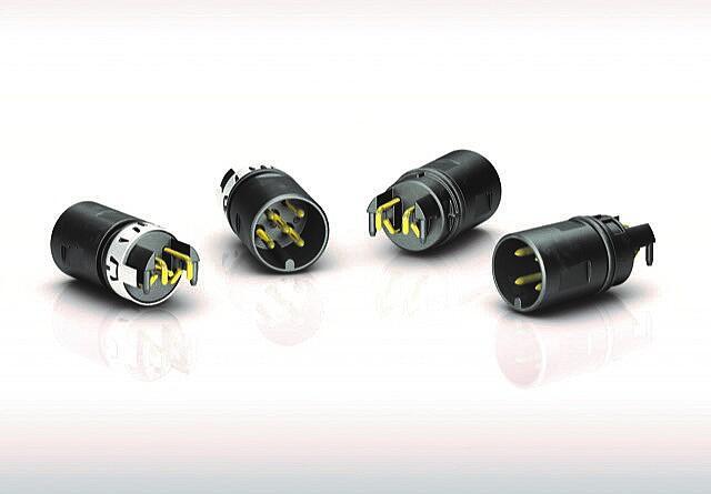
The PCB on the center axis
In classic PCB mounting, the connector sits on top of the board. The overall height of the assembly is therefore the sum of both – and in round housings, this sum determines the possible diameter. The angled M12-A panel-mount connector follows a different principle: it receives the PCB at its front edge, the contacts reach through from above and below, and the connector's axis lies in the plane of the board. In a cylindrical housing, the connector axis therefore coincides with the housing axis. The mounting is designed for PCB thicknesses of 1 to 2 mm.
Application: sensors in tubular housings
The advantage is most evident with sensors in tubular housings. Here, the diameter is dictated by the installation situation, and the electronics must fit onto a narrow circuit board. The populated PCB is inserted into the tube connector-first; the electrical interface then sits centered at the front face. Because the connector does not build up on top of the board, the available cross-section for the electronics is preserved – or the housing can be one size smaller. In addition to the “surface-mounted connector” solution, it is often the case, especially with sensor tubes, that panel-mount connectors with straight contacts are used; these are hand-soldered to wires, which in turn contact a circuit board. This manual soldering step is eliminated, saving time and effort.
Besides sensors in tubular housings, this design is typically used wherever limited installation space meets a standardized M12 interface:
- Level, distance, and pressure sensors
- Light barriers and position switches
- Measuring transducers in cylindrical housings
- Fieldbus and peripheral devices with tight installation space
Processing without special steps in manufacturing
The second benefit lies in manufacturing. THR technology allows soldering in the standard reflow process, eliminating a separate soldering step for the connector. The integrated pick-up surface makes the component graspable for the pick-and-place machine, so it runs through the line together with the rest of the assembly. For manufacturers with high volumes, this means less manual work, fewer process steps, and reproducible solder joint quality.
Technical features at a glance
- Design: angled, front-mounted, centric PCB mounting (midmount)
- Interface: M12 A-coded per DIN EN 61076-2-101, 4- and 5-pin
- Variants: shielded or unshielded, with or without O-ring
- Termination: THR, reflow-solderable, with integrated pick-up surface
- PCB thickness: 1 to 2 mm
- Protection rating: IP68 when mated and locked
- Electrical ratings: Rated voltage 60 V, rated impulse withstand voltage 1,500 V
- Environment: -40 °C to +85 °C, more than 100 mating cycles
- Materials: Gold-plated contacts, contact body LCP per UL 94 V-0
Expert statement
“Anyone who has to fit sensor electronics into a tubular housing fights for every millimeter. With the angled M12-A for centric PCB mounting, we take exactly that millimeter out of the equation – without the customer having to touch their production line. That, for us, is the real point: a design that creates space in the device and requires no special steps in production,” says Philipp Zuber, Head of Product Management at binder.
Conclusion
With the angled M12-A panel-mount connectors for centric PCB mounting, binder is expanding its automation portfolio with a design that serves two requirements at once: a compact height in the device and automated processing in manufacturing. The connectors are compatible with existing solutions already on the market. This gives device manufacturers an additional source for an interface that has so far only been available to a limited extent.